Sunday, April 9, 2017

Economiser and its types

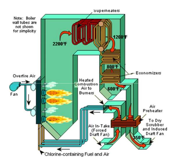
An economiser is a mechanical device which is used as a heat exchanger by preheating a fluid to reduce energy consumption. In a steam boiler, it is a heat ex-changer device that heats up fluids or recovers residual heat from the combustion product i.e. flue gases in thermal power plant before being released through the chimney. Flue gases are the combustion exhaust gases produced at power plants consist of mostly nitrogen, carbon dioxide, water vapor, soot carbon monoxide etc. Hence, the economiser in thermal power plants, is used to economise the process of electrical power generation, as the name of the device is suggestive of. The recovered heat is in turn used to preheat the boiler feed water, that will eventually be converted to super-heated steam. Thus, saving on fuel consumption and economising the process to a large extent, as we are essentially gathering the waste heat and applying it to, where it is required. Nowadays however, in addition to that, the heat available in the exhaust flue gases can be economically recovered using air pre-heater which are essential in all pulverized coal fired boiler.


Working Principle of Economizer


As shown in the figure above, the flue gases coming out of the steam boiler furnace carry a lot of heat. Function of economiser in thermal power plant is to recover some of the heat from the heat carried away in the flue gases up the chimney and utilize for heating the feed water to the boiler. It is simply a heat ex-changer with hot flue gas on shell side and water on tube side with extended heating surface like Fins or Gills. Economisers in thermal power plant must be sized for the volume and temperature of flue gas, the maximum pressure drop passed the stack, what kind of fuel is used in the boiler and how much energy needs to be recovered. When the water is boiled in steam boiler, the steam is produced which is then super-heated after which it is passed to the turbines. Then the exhausted steam from turbine blades, is passed through steam condenser of turbine in which the steam is condensed and this condensed water then is pre warmed first in feed water heater then in it before re-feeding in boiler. It is placed in the passage of flue gases in between the exit from the boiler and the entry to the chimney. In this a large number of small diameter thin walled tubes are placed between two headers. The flue gases flow outside the tubes usually in counter flow.

Classification of economizers: 

1. Based on construction 

(i) Plain tube type economizers: The external surface of tubes is kept clean and free from soot by soot scrapers moving up and down the economizer tubes. Otherwise heat transfer resistance is increase and efficiency of economizer decreased.


(ii) Gilled tube type economizers: Rectangular gills are provided on the bare tube walls to increases the heat transfer surfaces .


2. Based on part of steam generation
(i) Steaming type economizers: some part of the water (about 5 to 7%) to be converted into steam during its passage through the economizer.

 (ii) Non-steaming type economizers: While in case of non steaming economizer feed water is heated within 75% of the saturation temperature of the boiler.

3. Based on location of economizers 

(i) Independent economizers: economizer is installed outside the boiler house at any convenient place

(ii) Integral economizers: economizer is installed close to the boiler 

4.Types of Economiser Based on boiler Efficiency

(i) Non condensing Economiser
     The most common type of economiser used in thermal power plant is the non condensing thermal power plant. They are Heat exchanger tubes with fins around them in the form of spiral and they are loacated inside the duct at the exit region of the boiler.In this economiser used for reducing the flue requirement of boiler by transfering the heat from the flue gas to the feed water inside the tubes. These are used in coal fired thermal power plant where the temperature of the flue gas can be reduced to 120 deg c and not beyond it.This type of Economiser increases the efficiency by 3-6%

(ii)Condensing Type Economiser: They are used in nautral gas fired thermal powerplant. They reduced the fluegas temperature below condensation temperature as low as 25 deg c. They increase the boiler efficency by 10-15%. while using the condensor the fuel should not contain sulphur.
Advantages of economizers:

 (1) It improves the boiler efficiency. It has been found that about 1% efficiency of boiler is increased by increasing temperature of feed water by 6 °C with help of economiser. 

(2) It reduces the losses of heat with the flue gases, The temperature of flue gases is about 370°C to 540°C at exit of last superheater or rehea ter, having large amount of heat energy which otherwise otherwise would have been wasted. 

(3) It reduces the consumption of fuel. It has been estimated that about 1% of fuel costs can be saved for every 6 °C rise in temperature of the boiler feed water. 

(4) It reduces thermal stresses in the boiler due to reduced temperature differential in the boiler.

Friday, November 11, 2016

Hydro Pnuematic Accumulators

The accumulator are pressure storage reservoir in which non compressible fluids are stored under pressure. accumulators are connected to pump discharge lines for compensating for loss of fluid pressure in the hydraulic circuit.
They are used for
1. Emergency operation
2. pulsation Damping

TYPES OF ACCUMULATOR
1. Bladder type accumulator
2. Diaphragm type accumulator
3.Piston type accumulator

Bladder Accumulator 
Fluids are not in compressible and cannot store pressure energy, but gas can be compressed so it is used for storing fluids in accumulator.The accumulator consists of a shell. The shell consist of fluid section and gas section. The gas section has a bladder which is filled with nitrogen gas. Surrounding the bladder is the fluid.The bladder can be expanded and compressed for storing and releasing the fluid.The fluid section is connected to the hydraulic section ie poppet valve for drawing the fluid into the accumulator when the fluid pressure is higher and compresses the bladder with gas.so the fluid is stored inside the accumulator.when the fluid pressure in the line drops the bladder expands and forces the stored fluid in the hydraulic circuit with the pump flow

The accumulator bladder is pre pressurised with nitrogen gas upto 2.3bar. The bladder gas pressure is set 70%  to 80 %of the hydraulic circuit pressure.

Diaphragm type accumulator
These accumulators have a rubber plate or diaphragm as the separating element. This element is welded or screwed together between two spherical shells (or compartments). The compartment above the diaphragm is filled with nitrogen. The compartment below is directly connected to the hydraulic circuit. Diaphragm accumulators are useful if the required fluid storage capacity is low (i.e. 4 litres or less).
Diaphragm accumulators have most of the advantages of bladder-type units, but can handle gas compression ratios of up to 8:1. However, they are limited to smaller volumes, and their performance can sometimes be affected by gas permeating across the diaphragm.


Special Equipment are available to check the pressure of the nitrogen and it should be check once per year. If nitrogen pressure is high it can be reduced. By using mobile nitrogen charging devices the pressure can be added or refilled

Friday, November 4, 2016

PUMP CAVITATION

CAVITATION
   
            When a liquid boils at a suction line of a pump it is said to be cavitation. As the liquid boils it forms cavity of gases in the suction line. this happens when liquid pressure is well below the vapour pressure of the liquid.Boiling starts when pressure of the liquid is reduced to vapor pressure of the liquid at the actual temperature.

Vapour pressure of water: 
The pressure at which the water turns into vapor at the given temperature.
for example: water turns into vapor at 40deg at pump suction pressure below 0.07 bar, so pump suction pressure should not go below 0.07 bar at 40 deg to avoid cavitation.

Causes of cavitation
Cavitation can causes serious damage to the pump in the form of vibration and abnormal sound. cavitation leads to bearing and mechanical seal failure, shaft breakage , pitting on the impeller.
The damage occurs when these bubbles pass to the high pressure region of the pump.The bubbles explode at the vanes of the pump.

Problems due to cavitation
Loud noise
reduced flow
pitting formation in the impeller

Net positive suction head
The Minimum pressure required at the suction port of the pump to keep the pump from cavitating

Net positive suction head available
The pressure available at the suction side of the pump and it should be calculated and it should be more than NPSH R

Net positive suction head required
It is the minimum pressure required at  the pump suction to keep the pump away from cavitation and to be provided by the manufacturer.

Net positive suction lift
If the pump is positioned above the tank it has some net positive suction head. if the pump is raised above the tank the net positive suction head reduces and at some point the head becomes zero and the fluid starts to evaporate.


Monday, October 24, 2016

Thermal Power plant interview questions and answer

1.What are boiler mountings?
   Ans: boiler mounting are mounted on the boiler itself and mandatory required for safe and proper operation of boiler
1.water level indicator
2.pressure Gauge
3.safety valve
4. Blowdown valve
5.Feed Check valve
6.Main steam Stop valve

2.what are boiler accessories?
Boiler accessories are components that are attached to boiler and used for working of boiler and increasing its efficiency
1.Feed pump
2. Economizer
3. Air preheater
4.Fans
5. super heater
6.Ash handling system

3.what type of boiler does not need steam drum?
   Ans: Super critical Boiler

4.Why it is unsafe to have high water condition in drum?
    Ans: High Drum Level does not allow efficient steam water separation and makes water to carry over with steam to turbine.

5.What are the causes for boiler tube failure?
   Ans: Due to long term overheating due to scales and deposits formed on the outer surface of tubes
          Short term overheating , occurs due to flow restriction in the tube
          Thermal stress and shock  , occurs due to frequent start and stops
           Erosion, occurs due to coal , oil, ash
           corrosion
           Creep occurs due to constant stress of material at high temperature

6.Why boiler is purged every time before starting?
    To remove any left over fuel in boiler which leads to explosion

7. What are the uses of oil firing?
    1.warming up of boiler due to cold start up
    2.increase the furnace core temperature to switch to coal firing
    3. Stabilizing flame when interruption occurs to coal firing
    4.Useful during low load operation

8. What is the pressure and temperature of super critical boiler?
    Boiler operating pressure is more than critical pressure (221.2 bar and 375 deg temp) is called super         critical boiler. At this point both steam and water have same density.

9.how to find incomplete combustion in boiler
    high carbon oxide content at flue gas at exit

10 The efficiency of Rankine cycle is in the range of
     35-45 %

11. On which factor does calorific  valve of coal depend upon?
      Ash content

12.What is Thermal Energy?
     The ratio of heat energy to the turbine to heat of coal combustion
   

Tuesday, October 18, 2016

Impulse cum Reaction Turbine

Steam Turbine is considered as the the heart of the turbine. Turbine is used to Convert the Thermal energy to Mechanical Energy. Thermal Energy is the Steam and Mechanical Energy is used to rotate the steam turbine.

Thermal Energy = kinetic Energy in steam + pressure energy in steam + temperature of steam
Enthalpy = pressure energy + temperature of steam

so, Thermal Energy = kinetic energy + entalpy of steam


Impulse Turbine
Impulse Turbine is the first stage in the steam turbine. Its is the control stage. Here the blades will like cup shaped. The steam enters through the inner casing nozzle at constant pressure and temperature and enters the stationary blades. The stationary blades acts as a nozzle, it increases the kinetic energy and decreases the pressure of the fluid. Fluid with high velocity impacts the rotor and moves it. As the fluid strikes the moving blades in the rotor, the kinetic energy decreases and pressure remains constant because here the kinetic energy is used to convert into mechanical energy

Reaction Turbine
The remaining stages in the turbine are reaction turbine. The steam after leaving the impulse stage enters the reaction stationary blades. Here both stationary and rotary blades acts as nozzle. when steam enters stationary blades velocity increases and pressure decreases.The fluid with increased velocity enters the rotary blades , here the pressure decreases ad the velocity also decreases as both pressure and kinetic Energy are required to convert into Mechanical Energy.The entalpy and kinetic energy decreases through the stages
.

Impulse Turbine Reaction Turbine
In stator stages velocity increases and pressure decreases In stator stages velocity increases and pressure decreases


In Rotary Stages velocity decreases and pressure remains constant
In Rotary stages velocity decreases and pressure decreases


Here Kinetic Energy is only required to convert to Mechancial Energy
Here Both pressure Energy and Kinetic Energy is used to convert into Mechanical Energy


Here stationary blades only acts as nozzle
Here  both stationary and rotary blades acts as nozzle


Saturday, October 15, 2016

Gear box backlash

The Gear box backlash is the clearance or gap between the two mating gear tooth.
The backlash can be measured with dial gauge , feeler gauge or lead wire.The Dial Guage pointer is kept at Driven gear face and the drive gear is locked. Then the driven gear is moved which shows the backlash valve in the dial gauge.
Another Method is keeping the lead wire in between the two faces of the mating gear and allowed to mesh.After the lead wire compresses it is measured with the micrometer which shows the backlash reading.

Reasons for Gear Backlash increase
Due to gear face wear after running so many hours
Due to bearing Radial wear
If the center distance between two gear is high

Back Lash and Gear box Clearance are different . Gearbox clearance is the space between the addendum circle of one gear to the deddendum circle of another gear

Backlash valve for normal gearbox 0.18-0.3mm for heavy load < 3mm
There should be sufficient backlash for allowing lubrication to gears and compensate mialignments

GEAR RUN OUT

Gears can be eccentricity. eccentricity is caused due to the gear teeth profile. All gear teeth cannot be manufactured accurately with proper dimension. they can be +or- 0.5 mm. so due  to this eccentricity happens. Eccentricity can cause vibrations.

A badly Eccentric tooth may cause abrupt gear failure. so the run out must be checked. Dial gauge is used for checking the rut out valve.

The Dial gauge Tip is inserted between the tooth and the gear is rotated tooth by tooth, The high eccentricity point will shoe high valve and its is noted.

The high run out reading also indicate that the bearing clearances have increased and must be replaced.
The problem in the bearing can be found out by run out inspection

Run out value <0.2mm for medium duty gears and 0.4mm for heavy duty gears